Wan Technologies
Frame Relay, ISDN, LAPB, LAPD, HDLC, PPP, PPPoE, Cable, DSL, MPLS, and ATM.
The only WAN protocols configured on a serial interface are HDLC, PPP, and Frame Relay.
Types :
Leased Lines T1, T3 dedicated connection. Interface: serial. Encapsulation: hdlc, ppp (for mixed), slip.
Curcuit switched less expensive, through tel line ISDN, Dialup. Interface: BRI. Encapsulation: hdlc, ppp (for mixed), slip.
Packet switching is a combination always on connection. Encapsulation: synchronous x.25, Frame, ATM
Corp#config t
Corp(config)#int s0/0/0
Corp(config-if)#encapsulation ?
atm-dxi ATM-DXI encapsulation
frame-relay Frame Relay networks
hdlc Serial HDLC synchronous
lapb LAPB (X.25 Level 2)
ppp Point-to-Point protocol
smds Switched Megabit Data Service (SMDS)
x25 X.25
Frame Relay - A packet-switched technology, speed from 64Kbps up to 45Mbps (T3).
Provides features for dynamic bandwidth allocation and congestion control.
ISDN - Integrated Services Digital Network It is a set of digital services that transmit voice and data over existing phone lines.
LAPB - Link Access Procedure, Balanced . Creates a tremendous amount of overhead due to its strict time-out and windowing techniques.
LAPD - Link Access Procedure, D-Channel. Is used with ISDN at the Data Link layer (layer 2) as a protocol for the D (signaling) channell.
HDLC - High-Level Data-Link Control. Creates very little overhead compared to LAPB
PPP - PPP can be used to create point-to-point links between different vendors’ equipment
MPLS - Multiprotocol Label Switching — мультипротокольная коммутация по меткам) — механизм передачи данных, который эмулирует различные свойства сетей с коммутацией каналов поверх сетей с коммутацией пакетов
PPPoE - encapsulates PPP frames in Ethernet frames, usually used in conjunction with ADSL services. Has authentication, encryption, and compression features
Cable - Hybrid fibre-coaxial, or HFC over a cable TV (CATV) line, up to about 27Mbps download rate.
link
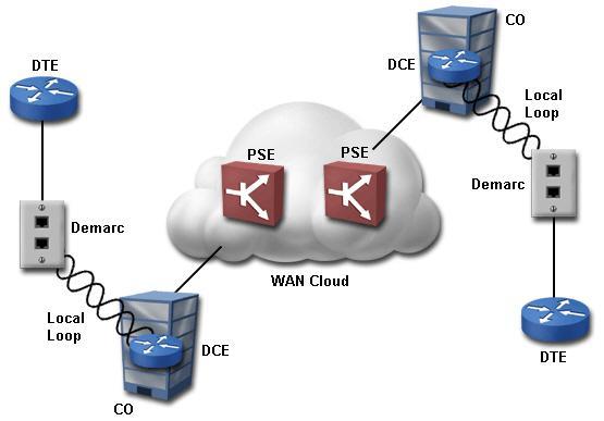
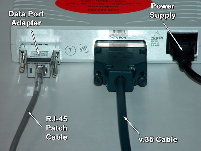
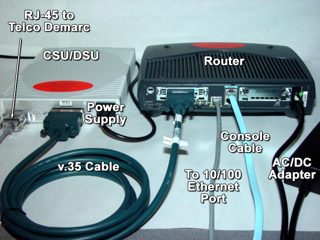
Data terminal equipment DTE - equipment at the customer's site and marks the point of entry between the LAN and the WAN. DTEs are usually routers, but computers and multiplexers can alsoact as DTEs
Data circuit-terminating equipment DCE - device that communicates with both DTEs and the WAN cloud. A modem or CSU/DSU at the customer site is often classified as a DCE, because it provides upplies clocking signals to DTEs
Packet-switching exchange (PSE) A switch on a carrier's packet-switched network. PSEs are the intermediary points in the WAN cloud
Local loop - Cable that extends from the demarc to the central telephone office. The demarc media is owned and maintained by the telephone company. Typically, it is UTP, but it can also be one or a combination of UTP, fiber optic, or other media
Customer premises equipment CPE - equipment owned by the subscriber
Demarcation point - The point where the telephone company's telephone wiring connects to the subscriber's wiring. The demarc can also be called the network interface or point of presence
Co - Central office
Toll network - trunk line inside a WAN provider’s network
Leased lines - point-to-point or dedicated connection, lines up to 45Mbps
Circuit switching - uses dial-up modems or ISDN and is used for low-bandwidth data transfers, only pay for the time you actually use
Packet switching - allows sharing bandwidth with other companies.Data transfers are the bursty type. Examples: Frame Relay and X.25
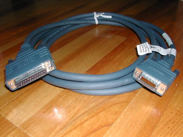
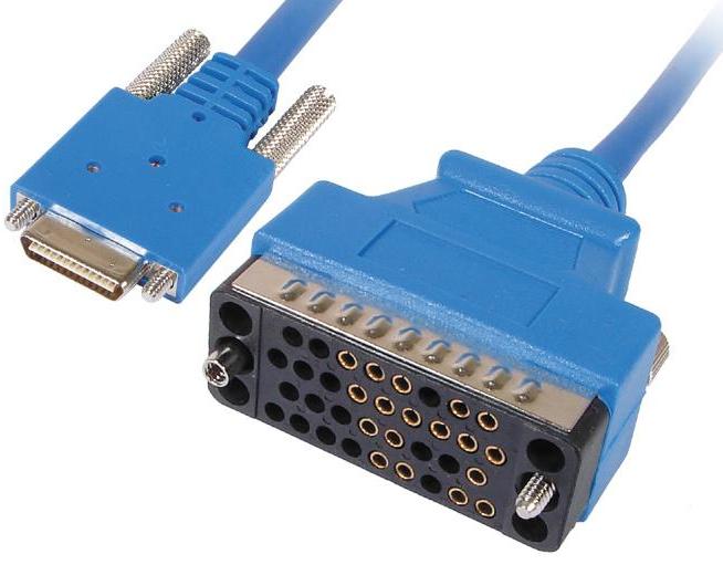
Pinout Diagrams
In the Integrated Services Digital Network (ISDN), there are two levels of service: the Basic Rate Interface (BRI), intended for the home and small enterprise, and the Primary Rate Interface (PRI), for larger users. Both rates include a number of B-channels and a D-channel. Each B-channel carries data, voice, and other services. The D-channel carries control and signaling information.
The Basic Rate Interface consists of two 64 Kbps B-channels and one 16 Kbps D-channel. Thus, a Basic Rate Interface user can have up to 128 Kbps service. The Primary Rate Interface consists of 23 B-channels and one 64 Kpbs D-channel in the United States or 30 B-channels and 1 D-channel in Europe.

| Plain Old Telephone Service (POTS) |
POTS service has the following characteristics:
- Existing wires use only one twisted pair
- Analog signals are used through the local loop
- A modem is required to convert digital signals to analog
- The line has an effective limit of 56 Kbps
You can also use the same physical wires for digital signaling. Multiple
digital channels are sent over the same physical wires. |
T-1
(a.k.a. DS-1) |
24 64-Kbps channels (used in the U.S.) |
T-3
(a.k.a. DS-3) |
672 64-Kbps channels |
| E-1 |
31 64-Kbps channels (used in Europe) |
| Public Switched Telephone Network (PSTN) |
56 Kbps |
POTS |
Analog |
Dialup over regular telephone lines |
| Leased lines |
56 Kbps |
POTS |
Analog |
Dedicated line with consistent line quality |
| X.25 |
64 Kbps |
POTS |
Analog |
Dedicated line
Variable packet sizes (frames)
Ideal for low-quality lines |
| Frame Relay |
1.54 Mbps |
POTS
T-1
T-3 |
Digital |
Variable packet sizes (frames) |
| Asynchronous Transfer Mode (ATM) |
1.2 Gbps |
Coaxial, twisted pair, fiber-optic |
Digital |
Fixed-size cells (53-byte)
High-quality, high-speed lines |
| Integrated Services Digital Network (ISDN) |
144 Kbps (BRI)
4 Mbps (PRI) |
POTS
T-1 |
Digital |
Basic rate operates over regular telephone lines and is a dialup
service
Primary rate operates over T-carriers |
| DSL |
6.1 Mbps
(1.544 or lower is more common) |
POTS |
Digital |
Operates using digital signals over regular telephone lines
DSL comes in many different flavors (such as ADSL and HDSL) |
There is no clear distinction between WAN services such as Frame Relay and
ISDN. For example, you can use Frame Relay protocol over ISDN lines. Once a
device connects to the WAN cloud, internal protocols can convert data traffic
into the necessary formats, then convert the data again at the other end.
PPP Facts
The following list represents some of the key features of the Point-to-Point
Protocol (PPP):
- It can be used on a wide variety of physical interfaces including
asynchronous serial, synchronous serial (dial up), and ISDN.
- It supports multiple Network layer protocols, including IP, IPX,
AppleTalk, and numerous others.
- Optional authentication is provided through PAP (2-way authentication)
or CHAP (3-way authentication).
- It supports multilink connections, load-balancing traffic over multiple
physical links.
- It includes Link Quality Monitoring (LQM) which can detect link errors
and automatically terminate links with excessive errors.
- It includes looped link detection that can identify when messages sent
from a router are looped back to that router. This is done through routers
sending magic numbers in communications. If a router receives a packet with
its own magic number, the link is looped.
PPP uses two main protocols to establish and maintain the link.
| Link Control Protocol (LCP) |
The Link Control Protocol (LCP) is responsible for establishing,
maintaining, and tearing down the PPP link. LCP packets are exchanged
periodically to do the following:
- During link establishment, LCPs are used to agree upon
encapsulation, packet size, and compression settings. LCPs also
indicate whether authentication should be used.
- Throughout the session, LCPs are exchanged to detect and correct
errors or to control the use of multiple links (multilink).
- When the session is terminated, LCPs are responsible for tearing
down the link.
A single Link Control Protocol runs for each physical connection. |
| Network Control Protocol (NCP) |
The Network Control Protocol (NCP) is used to agree upon and
configure Network layer protocols to use (such as IP, IPX, or
AppleTalk). Each Network layer protocol has a corresponding control
protocol packet. Examples of control protocols include:
- IP Control Protocol (IPCP)
- CDP Control Protocol (CDPCP)
- IPX Control Protocol (IPXCP)
- AppleTalk Control Protocol (ATCP)
A single PPP link can run multiple control protocols, one for each
Network-layer protocol supported on the link. |
PPP establishes communication in three phases.
- LCP phase. LCPs are exchanged to open the link and agree upon link
settings such as encapsulation, packet size, and whether authentication will
be used.
- Authenticate phase (optional). During this phase,
authentication-specific packets are exchanged to configure authentication
parameters and authenticate the devices. LCPs might also be exchanged during
this phase to maintain the link.
- NCP phase. NCPs are exchanged to agree on upper-layer protocols to use.
For example, routers might exchange IPCP and CDPCP packets to agree upon
using IP and CDP for Network-layer communications. During this phase, LCPs
might continue to be exchanged.
Configure Username/Password Combinations
- Configure both routers with a username and password
- The username identifies the hostname of the remote router
- The password configured on both routers must match
When using PAP, the password will be sent and used for authentication. When
using CHAP, the password identifies the shared secret that is used (the password is not sent during authentication).
SFO(config)#hostname LAX password cisco5
SFO(config)#int s0
SFO(config-if)#encap ppp
SFO(config-if)#ppp auth pap
Frame Relay
Frame Relay Facts
Frame relay is a standard for packet switching WAN communications over
high-quality, digital lines. Frame-relay networks:
- Provide error detection but not error recovery. It is up to end devices
to request a retransmission of lost packets.
- Can provide data transfer up to 1.54 Mbps.
- Have a variable packet size (called a frame) .
- Can be used as a backbone connection to LANs.
- Can be implemented over a variety of connection lines (56K, T-1, T-3).
- Operate at the Physical and Data Link layers of the OSI model.
When you sign up for Frame Relay service, you are assigned a level of service
called a Committed Information Rate (CIR). The CIR is the maximum guaranteed
data transmission rate you will receive on the Frame Relay network. When network
traffic is low, you will likely be able to send data faster than the CIR. As
network traffic increases, priority is given to data coming from customers with
a higher CIR, and the effective rate may drop. In any case, you are guaranteed
to have at least the amount of bandwidth specified by the CIR.
You should be familiar with the following concepts about how Frame Relay
networks send data.
- Routers connect to a Frame Relay switch either directly or through a
CSU/DSU.
- Frame relay networks simulate an "always on" connection with PVCs.
- Sending routers send data immediately without establishing a session.
- Frame Relay switches perform error checking but not correction.
- Corrupted packets are simply dropped without notification.
- Packets travel through the Frame Relay cloud without acknowledgments.
- Error correction is performed by sending and receiving devices.
- Frame Relay switches begin dropping packets when congestion occurs.
- Congestion is the most common cause of packet loss on a Frame Relay
network.
- Packets are discarded based on information in the Discard Eligible (DE)
bit.
- Frame Relay switches send Backward Explicit Congestion Notification (BECN)
messages to slow data transfer rates.
Frame Relay Protocols
Most Frame Relay installations involve connecting to a Frame Relay
network through a T-1 line. The router connects to a CSU/DSU, which is
connected to the Frame Relay network. The Frame Relay network is made up of
multiple switches for moving packets.
You should be aware of the following Frame Relay protocols:
| Data-Link Connection Identifiers (DLCIs) |
Like an Ethernet MAC address, DLCIs identify each virtual
circuit.
- The DLCI ranges between 16 and 1007.
- The DLCI represents the connection between two frame relay
devices.
- The Frame Relay service provider assigns the DLCI when the
virtual circuit is set up.
- Each DLCI is unique for the local network, but not for the
entire WAN. In other words, the same DLCI number can be used
multiple times in the entire network to identify different
devices.
|
| Local Management Interface (LMI) |
Local Management Interface (LMI) is a set of management protocol
extensions that automates many Frame Relay management tasks. LMI is
responsible for managing the connection and reporting connection
status. LMI can:
- Maintain the link between the router and the switch.
- Gather status information about other routers and
connections on the network.
- Enable dynamic DLCI assignment through multicasting support.
- Make DLCIs globally significant for the entire network.
Although DLCI numbers are only locally significant, through LMI
these numbers can be globally significant (i.e. the same number
is used throughout the entire network to identify a specific
link).
Cisco routers support three LMI types: Cisco, ANSI, and Q933a. |
When you connect a router to the Frame Relay network, the router
interface has a direct line to the Frame Relay switch at the service
provider. Although there is only one physical path between the router and
the switch, Frame Relay supports multiple virtual circuits. When configuring
a Frame Relay connection or circuit, you have the following options:
- Point-to-Point. A point-to-point link simulates a direct connection
with a destination device. With a point-to-point connection, the circuit
is configured to talk to only one other device.
- Multipoint. A multipoint link configures each circuit to communicate
with more than one destination device. The same circuit is used for
multiple conversations.